|


| |
TIME CODE &
CAPTION BOARDS FOR THE PCI-EXPRESS BUS
|
Our fifth generation of time code
boards. These boards fit into PCI Express x1 through x16 slots, with both
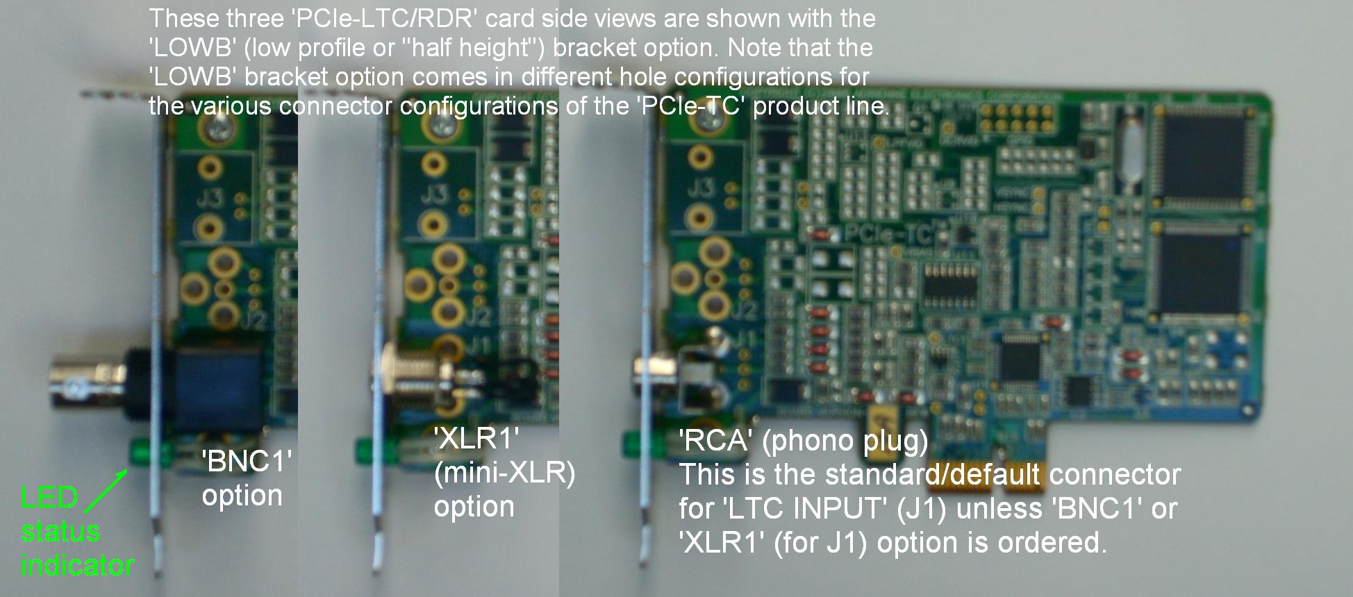
full height brackets (as shown at right) and low profile brackets (the no-cost LOWB option, see
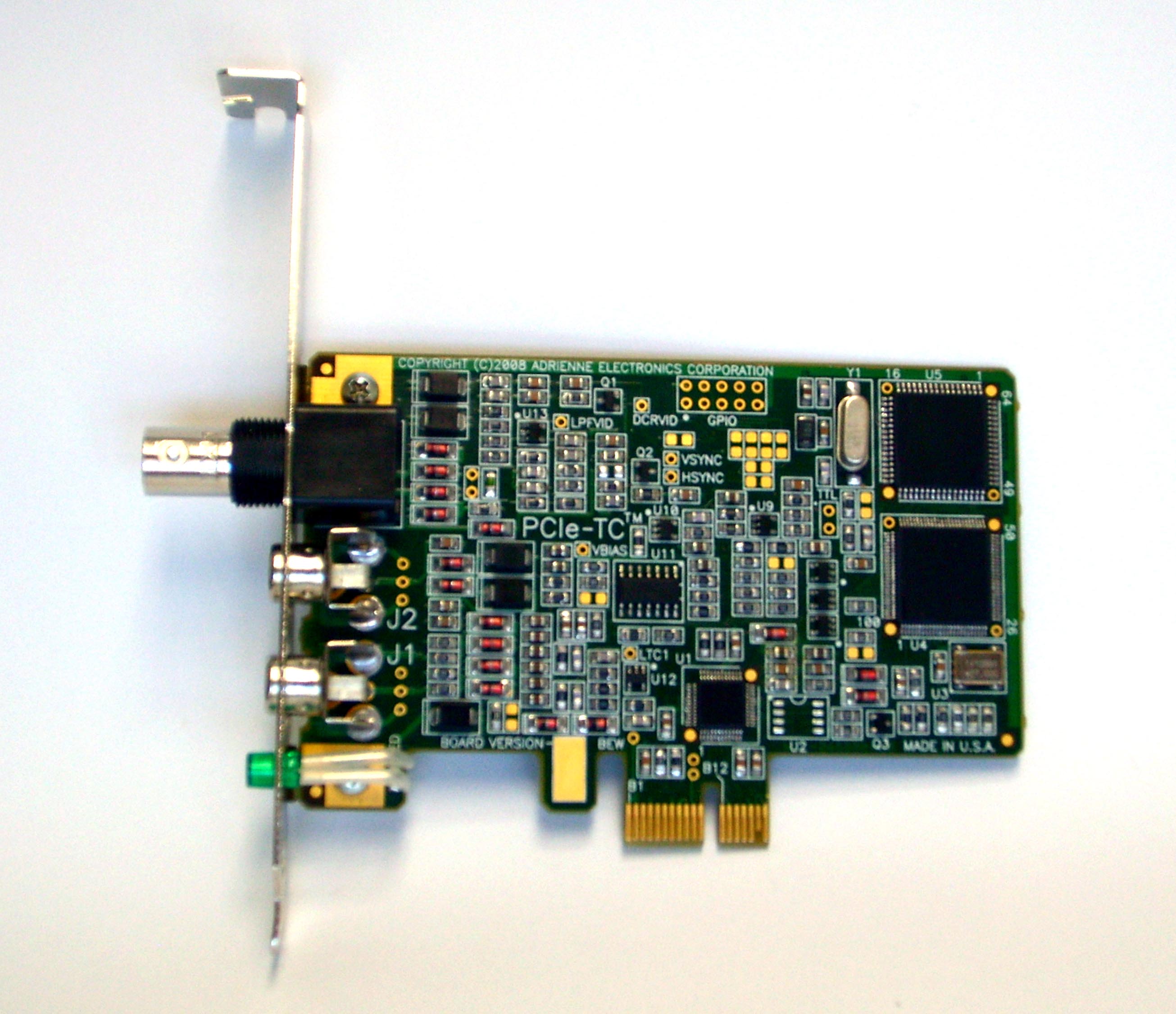
pictures below) available. All boards include a high performance
on-board processor, a green-colored external time code status LED,
system diagnostics, in-system electronic firmware updates if ever needed, plug and
play installation (no jumpers), software drivers, full RoHS
compliance, full FCC and CE-Mark approval, and automatic
SMPTE/NTSC(30fps), EBU/PAL(25fps), and FILM(24fps) operations.
Analog video circuitry can synchronize to 13 different video
standards, including 720p and 1080i signals having tri-level sync
pulses. RCA jacks are standard for LTC, and a BNC connector is used
for video/VITC. 4-channel GPIO option available for external logic
interfacing. Large order customization may be available. See details below for
pricing, additional model/function and connector option information. |
 |
Documentation / manuals / software
available on the 'Downloads' page.
These PCI express models of time code boards use
the same programming interface (DLL) as our PCI-TC & USB-TC time code device
families. Software that is written for this device family should also work
with the other device families (except for where supported features vary (ie:
GPIO, OSD, VITC Gen)) for the basic time code reader and LTC generator
functions, etc..
| PCIe-LTC/RDR |
LTC reader,
bi-directional, 1/10x to 80x, simultaneous time and user
bits, DF/NDF. The PCI express bus equivalent of our older PCI-LTC/RDR board.
See the pictures and option information below for additional
connector option configurations. This version has only one
connector at the 'J1' position. An RCA connector is the default
(standard). |
| PCIe-LTC/RGA |
LTC
reader/generator. Adds LTC generator and regenerator
capabilities to PCIe-LTC/RDR. LTC generator can freerun or
synchronize to LTC input, SD analog video, or HD analog video.
LTC reader/generator. Can read and generate LTC simultaneously. The PCI
express bus equivalent of our older PCI-LTC/RG1 board, but
without video (looping) output connection.
(See the picture above. Note that the above picture has the
default RCA connectors at J1 (LTC Input) and J2 (LTC Output)).
See the pictures and option information below for additional
connector option configurations. This version has three
connectors. The BNC connector shown in the above picture is the
video input (J3). |
| PCIe-LTC/RDV |
LTC reader
with analog video sync input. Same as PCIe-LTC/RDR above,
plus can generate a hardware interrupt at the start of every analog video field or frame.
Cannot read VITC or L21 data. |
| PCIe-VLTC/RDA |
LTC/VITC time code +
L21 data reader. Can read LTC, analog (NTSC and PAL) VITC, and
NTSC L21 (caption) data simultaneously at PLAY speed. Reads
analog VITC at -1x to STILL to +3x, bi-directional. Automatic or
programmable VITC line selection.
The PCI express bus equivalent of our older PCI-VLTC/RDR and
PCI-21VL/RDR boards, but without video (looping) output
connection. See the pictures and option information below for
additional connector option configurations. This version has two
connectors. The BNC connector shown in the above picture is the
video input (J3). There is no connector at the 'J2' position for
this version. |
| PCIe-VLTC/RG2 |
LTC/VITC time code +
L21 data reader and LTC generator. Combines PCIe-LTC/RGA and
PCIe-VLTC/RDA, plus has analog VITC-to-LTC
translator mode. The PCI express bus equivalent of our older PCI-VLTC/RG2 board,
but without video (looping) output connection. (See the picture
above. Note that the above picture has the default RCA
connectors at J1 (LTC Input) and J2 (LTC Output)). See the
pictures and option information below for additional connector
option configurations. This version has three connectors. The
BNC connector shown in the above picture is the video input
(J3). |
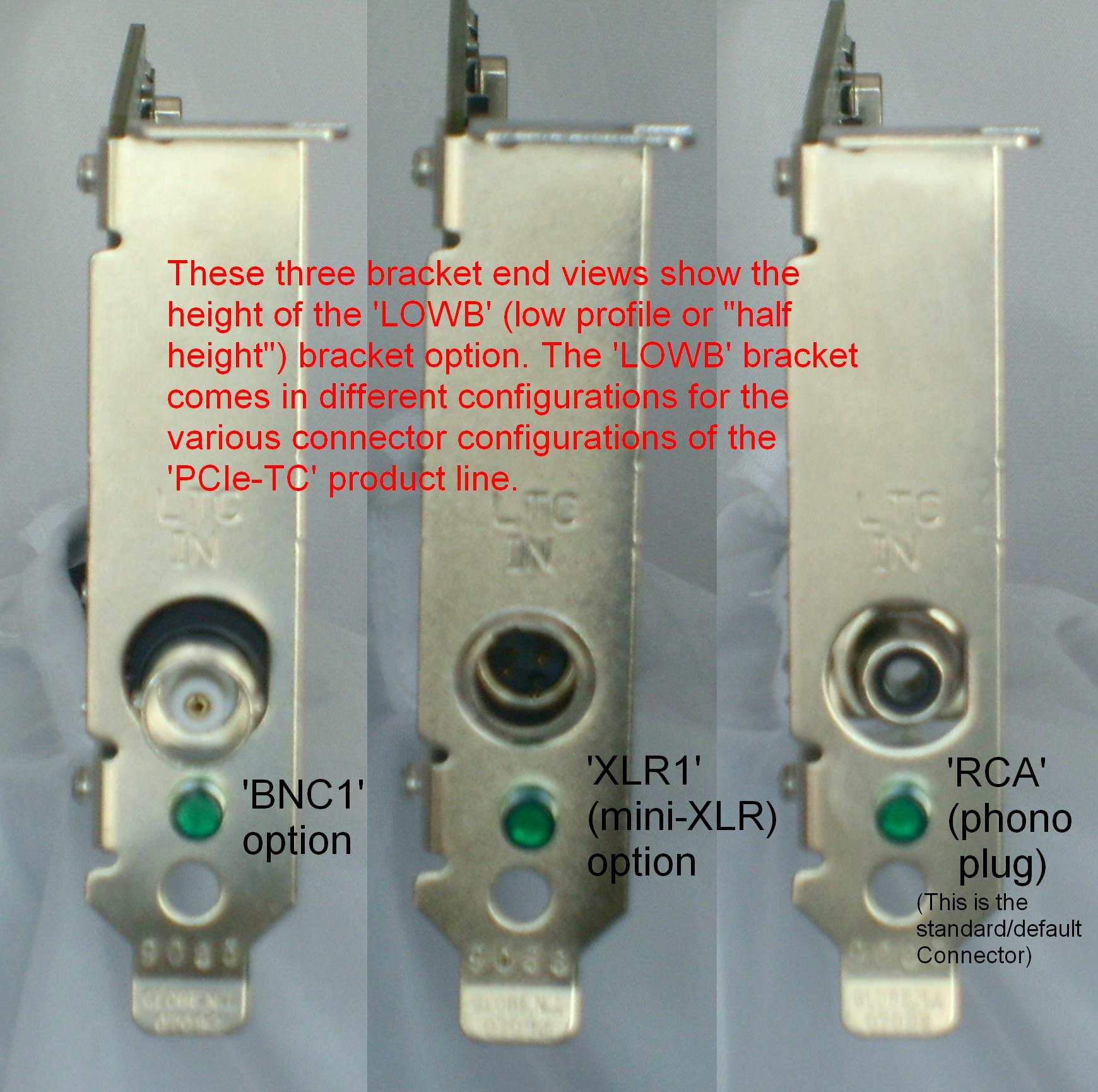
| LOWB / FULB |
All models ordered will come
with both Low Profile or 'half-height' Bracket
(LOWB) and Standard
Height (FULB) brackets at no
additional charge (n/c) if both of the brackets are available.
Some configurations don't have both LOWB and FULB versions. See the pictures below for more details.
Available for most of the (above) model and connector option
configurations (below). You may select the desired bracket
that you want installed from the factory. You may easily
change the bracket with the removal and reinsertion of a two
screws (and one or two nuts if XLR). Note also that OEM
configurations may not get both brackets. |
| GPIO |
Up to 4-Channels GPIO Port for External
Logic Interfacing. Contact factory
for configuration details and pricing. This option connects to a
cable at the location (shown in the picture ) at the top center
where the two rows of five holds are seen. (note: A 10 position
header will be inserted along with other components that
connects a cable that terminates witha DB9 "serial type"
connector). There is space in the full height bracket to hold
the 'DB9' connector. LOWB option users will need to find or
create a DB9 cutout/opening. Some applications for this option
include automatic triggering at specific (match) time codes and
hardware 'button' press detection. |
| BNC1 |
Use BNC Connector for LTC Input.
(note: Default connector is female RCA) |
| BNC2 |
Use BNC Connector for LTC Output.
(note: Default connector is female RCA) |
| XLR1 |
Use Mini-XLR Connector for LTC
Input. (mating plug included)
Mini-xlr.pdf
(note: Default connector is female RCA) |
| XLR2 |
Use Mini-XLR Connector for LTC
Output. (mating plug included) (note: Default connector is female RCA) |
Nomenclature Note - Those of you who have used our
conventional PCI-TC products in the past will notice a slight model
numbering change here. Where analog video is present, we have included
the letter “A” (analog) in the model number suffix. For example, PCIe-VLTC/RDA
is the functional equivalent of our older PCI-VLTC/RDR product. We
anticipate coming out with “S” (standard definition digital video) and
“H” (high definition digital video) functionally similar time code
boards in the near future, and want to have “room” for these new
products within our model numbering scheme when and if they become
available. The only exception is the PCIe-LTC/RDR, which by definition
will always be an analog product, so no suffix change was deemed
necessary in this case. Stay in touch for future developments.
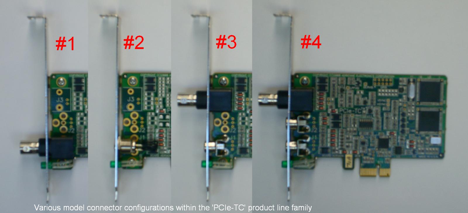
#1 - Shows the STANDARD bracket side
view of the model 'PCIe-LTC/RDR' with the 'BNC1' connector option.
#2 - Shows the STANDARD bracket side view
of the model 'PCIe-LTC/RDR' with the 'XLR1' connector option. Note that
this option also includes the mini-XLR mating plug, not shown.
#3 - Shows the STANDARD bracket side
view of the model 'PCIe-VLTC/RDA' with the default 'RCA' connector &
video BNC connector.
#4 - Shows the STANDARD bracket side view
of the model 'PCIe-LTC/RGA' (and/or 'PCIe-VLTC/RG2') with the
default 'RCA' connectors for the LTC input (J1) and LTC output (J2)
& video (BNC) connector (J3).
| |
'J1' Connector (LTC IN) |
'J2' Connector (LTC OUT) |
'J3' Connector (VIDEO IN) |
LOWB available |
GPIO available |
| PCIe-LTC/RDR |
RCA (default)
BNC1
XLR1 |
N/A |
N/A |
YES |
YES** |
| PCIe-LTC/RGA |
RCA (default)
BNC1
XLR1 |
RCA (default)
BNC2
XLR2 |
BNC |
YES |
YES** |
| PCIe-LTC/RDV |
RCA (default)
BNC1
XLR1 |
N/A |
BNC |
YES |
YES** |
| PCIe-VLTC/RDA |
RCA (default)
BNC1
XLR1 |
N/A |
BNC |
YES |
YES** |
| PCIe-VLTC/RG2 |
RCA (default)
BNC1
XLR1 |
RCA (default)
BNC2
XLR2 |
BNC |
YES |
YES** |
* Note: Due to stock bracket type limitations, the J2 connector type (if present)
must be the same as the J1 connector type.
** Note: At present the GPIO option is only supported directly by full height (FULB) brackets.
Contact the factory for possible options if you need a low profile (LOWB) bracket.
|
![[Company Logo Image]](_borders/aec_blue_short.GIF)